The motorized roller conveyor: in-line weight checking system
Construction of a pallet weighing system on a motorized roller conveyor.
Requirement
Build an in-line weight checking system in the logistics and handling sector.
The project is designed for the transit and weighing of pallets weighing up to 3000 kg with standard dimensions (1200x800 mm) on a motorized roller conveyor, in a system where the PLC is positioned well away from the weighing system.
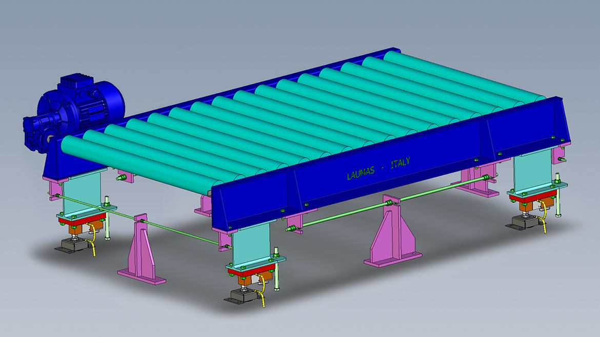
The roller conveyor has dimensions of 1500 mm x 850 mm and the unladen weight of just the mechanical structure (tare) is 1000 kg.
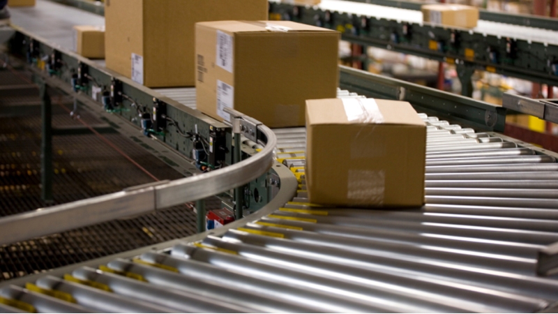
At the moment of weighing the pallet is to be placed on the roller conveyor by a lift truck, which is why it is necessary to design a static weighing system that takes into account any dynamic stresses caused by impact.
Why is it considered a static weighing system?
The pallet is weighed only when it stops.
Weighing then takes place with the pallet stationary, statically.
Our solution
The system consists of:
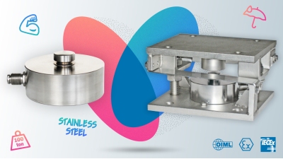
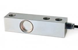
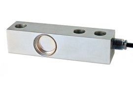
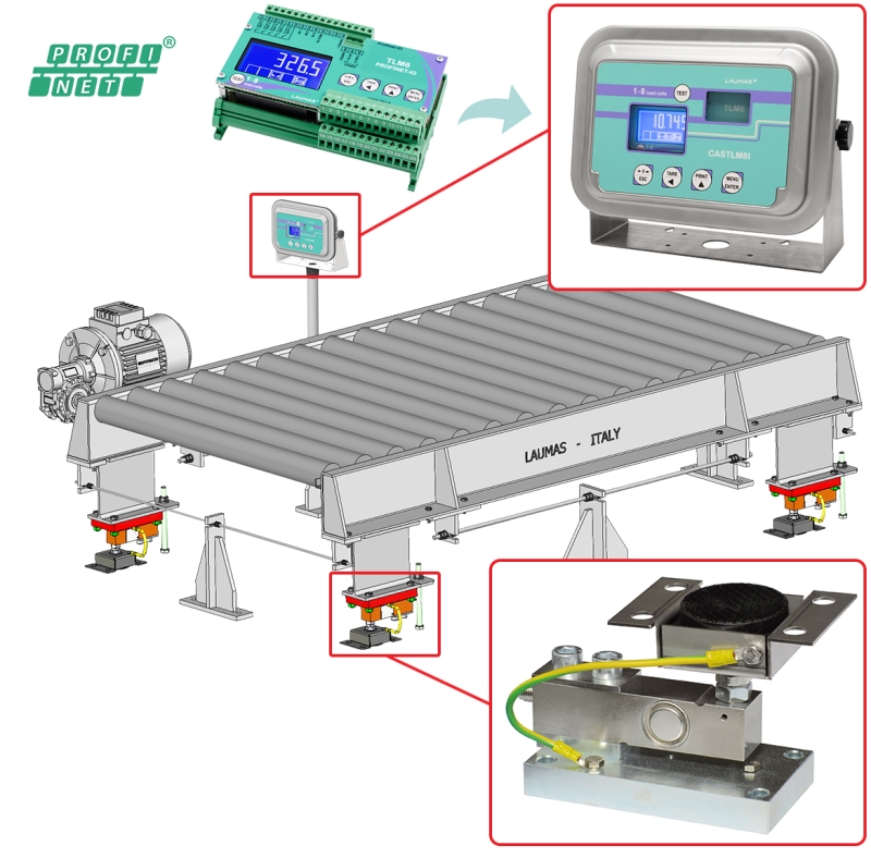
- 4 FTP 2000 kg shear beam load cells, located under the feet of the roller conveyor;
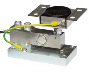
- 4 PV mounting kits with balls inside the feet and an anti-tilt system;
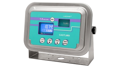
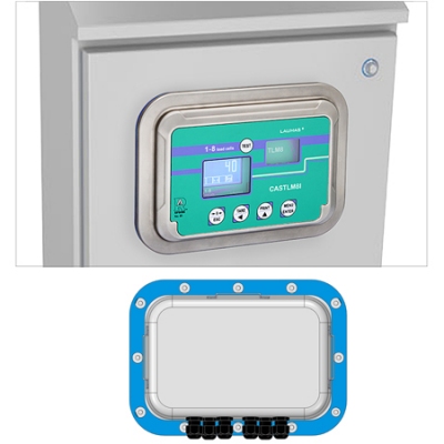
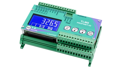
- 1 TLM8 Profinet IO weight transmitter in an IP69K stainless steel box;
- 4 threaded rods of approximately 50 cm, constrained to the floor and with the two ends constrained to the weighed structure
The total full scale of the system is 8000 kg. This is obtained by multiplying the capacity of each individual load cell (2000 kg) by the total number of load cells employed (4).
Knowing the system's full scale is very important. In order to avoid damage to the load cells due to accidental dynamic overloads, it is in fact good practice to have these types of systems work at a maximum of 60/70% of their capacity.
How do you know what capacity a weighing system is working at?
You have to subtract the gross weight from the total full scale, i.e. the sum of the weight of the structure alone (tare) and the maximum load to be weighed (net weight).
In this specific case: (8000) - (1000 + 3000) = 4000. The system is working at 50% of its capacity.
How does it work?
A motor and a photocell are also mounted on the structure.
A forklift truck rests the pallet on the motorized roller conveyor, which allows the pallet to slide to the point where the photocell is located.
When the pallet passes, the photocell is obscured and stops the system.
The pallet is thus located in the middle of the structure, right at the exact point where it is going to be weighed.
This is the moment when static weighing takes place and the measured weight is transmitted to the PLC via the Profinet fieldbus.
Once the weight has been recorded, the PLC instructs the system to restart.
Added value
With this solution and a few small precautions, the pallet is weighed in complete safety, avoiding potential damage to the weighing system caused by overloading or accidental knocks.
What makes the weighing system so safe and functional?
- The threaded rods, placed horizontally one on each side, which act as a constraint to the structure in all 4 directions and thus protect the load cells from accidental knocks and overloads;
- The TLM8 in a box, which avoids using the junction box for a connection in parallel of the load cells, providing advanced diagnostics
Installed “in the field”, close to the weighing system, it receives the electrical signal from the load cells and transforms it into the more robust Profinet signal, with which it safely reaches the PLC, even if it is located remotely. - PV is the safest mounting kit for this type of application: it is equipped with an anti-tilt constraint and its self-centering ball-based system transmits the weight vertically with no lateral friction.
By always bringing the force back to the middle, it helps the load cell remain constantly accurate and repeatable; - The PV feet, which make it possible to adjust the height of the accessory so that the structure rests perfectly on all 4 feet with no need to add any other stabilizing elements;
- The pre-sales consulting service for the customer, which is essential so as not to experience any issues in the future.
Our tips on how to correctly position the constraints against lateral forces to avoid mechanical friction ensure savings in terms of the time and cost of future assistance
RELATED PRODUCTS
CASTLM8I
Weight transmitters
CASTLM8I 3A
Weight transmitters
FT-P
Shear beam load cells
FTP
Shear beam load cells
PV - PVZ
Mounting Kits for load cells
TLM8 PROFINET IO
Weight transmitters

